Jan 112020


So here’s a little test of a ‘waveguide’ effect for LEDs.

This uses 5/8″ tube filled with clear silicone and I think it worked out pretty well. The video doesn’t capture the effect perfectly, it’s a little blown out, but you can get the idea that the light is being carried around the ring and looks a bit like it’s fluorescing from the liquid.

I started thinking about this awhile ago and finally got around to putting it all together. I initially started by trying to do tests with little sections of tubing attached to LEDs. Tried a few kinds of caulk and silicone but the only thing that really popped was the super clear silicone.

There’s a few tricks to the process. You have to fill the tube without any bubbles, which takes a bit of practice, patience, and elbow grease with a caulk gun. Then you have to smash the tube over the LED with enough excess to displace air and not allow any bubbles to form in between the LED and the tube, which blocks the light and dims the tube a lot. And you have to secure the tube to the LED to allow it to cure.

The simplest way to do all this was to just design and print the connector I had in my head for if the lighting effect worked. I made one section of tube and it looked pretty good, so I made this one with three sections.

The back ‘spine’ is hollow with a WS2812 strip doubled over so there’s an LED pointing left and right into each section of tube. The ‘waveguide’ carries light a few inches, enough for several configurations, but it can’t really replace EL wire or anything.

I didn’t include any STL’s or code because the silicone and acrylic is the trick, everything else is pretty simple to reproduce if you do this kind of thing, and if you don’t you should do that first before you start getting covered in silicone while playing with electronics.

Not sure why the video isn’t embedding but here it is.

https://youtu.be/fN1kAN9xcQ0

Jan 102020
 

This is an old ‘hearing test’ box that I gutted and used for various projects. This time it’s filled with older raspberry pi’s. I mainly use zero’s now, but wanted to make a sort of functional retirement home for my pi’s. This rig has:
(1) Raspberry Pi B (Original 256Mb RAM)
WiFi Bridge to LAN
(3) Raspberry Pi 2B+
~WebCam
~LCD
~RTL-SDR
(1) Acer Netbook running Raspian x86
~Interface
(1) 5-Port Ethernet Switch

I don’t turn it on much, but it’s a nice little package whenever I need to haul it out for something.
Figured it deserved a post so here’s that.

Aug 132019
 

I’m getting back around to some of my electronics stuff and I was discouraged that the Lolin32 I was using had been discontinued. In retrospect I probably should have used ESP8266 as the basis for WiFi LED control, but meh.

So anyway, I recently found a new board to get excited about, plus a few battery modules that haven’t actually come in yet. The ESP32-CAM has most of what I’d want in a board for simple bots; camera, wifi, and enough GPIO to control a few servos and an onboard flash LEDs. I got my first one in last weekend and spent it trying to get the basic functions for a FPV bot down.

Took me a while to cobble together the functions I needed from available docs and example code, but I’ve got a sketch that does the following:
~Connect to WiFi (SSID\PW hardcoded for now)
~Start camera stream
~Start UDP listener, parse and process incomming packets
~Servo motor control (2) currently
~LED control, onboard RED (ON\OFF) and WHITE (PWM)

Here’s the code I’ve got so far- be warned; like all my code- it’s a nightmare, but it works for me. I left some notes and links to other code I scavenged, but there’s a lot more to do and I honestly don’t even get how the camera stream is working in this sketch, but it does, so good enough for now.

The biggest downside of this board for me is it doesn’t have a built in USB interface so I have to use TX\RX pins to load code, but that’s not too big a deal. Though since only have the one ESP32-Cam at the moment and I’m leaving that one the breadboard for testing. I’ve ordered a few more since they’re so cheap- next one I get will go on this little robot platform I found online and printed. I actually found this design online some time ago and saved the files, but now I can’t figure out where I found it, so if anyone knows this design and has a link to it please let me know.

Hopefully I’ll post more because hopefully I’ll do more, but this is something and I figure if anyone else out there is messing with an ESP32-CAM out there they may find this marginally useful. If by some chance you are working with this board feel free to contact me, it’s got some great potential.

Aug 282017
 

IMG_20170827_201722IMG_20170827_201832

So I’ve been using Arduino Nano’s for a long time and my communications were pretty limited to
bluetooth and IR. I always wanted to use WiFi connection, but the expense and effort to integrate WiFi with Arduino was never really worth is. Enter the ESP8266- I actually made a few attempts to use it as a drop in replacement for the bluetooth modules I’m using, but I never got anything working the way I wanted.

So then I start seeing these ESP32’s and they look pretty sweet, but I wasn’t sure I wanted to take the leap when I was so comfortable in my little Nano world.

Then I see the Lolin32 ESP-32 board, with one major thing that set it apart- the battery connection and charging circuit. Game changer for me. I’ve been using USB battery packs forever because they’re pretty self-contained and nothing I could hack together would be as good as just plugging in the USB, but now I’ve got options.

So I got a couple of these Lolin32’s and I’ve had about a week to poke at them. I finally got a few of the puzzle pieces turned over so I think I’m ready to start redoing the old bluetooth LED FX stuff for the ESP-32.

So this post is mostly just to make notes and such so I don’t forget and maybe they’ll help someone else trying to get started with these chips.

Here’s some pics of my ‘first light’, got a little strip of LED’s controlled via a simple web server on the Lolin32.

NOTES \ STUFF I’VE FOUND SO FAR
~FastLED library isn’t there yet. They just updated it with ESP32 support but I still couldn’t get it working so I ended up using Adafruits Neopixel library. There are still some weird flickering and color issues, but for the most part the library works okay.
~Pin 0 is weird. Not sure what’s up with that but when you have anything connect to it the Lolin32 boots into a different mode so idk if you can use this pin as a normal GPIO

TO DO \ STUFF I PLAN TO DO LATER
~Going to figure out more about the deep sleep mode on these things
~Not sure if there’s a way to monitor the attached battery voltage, but that would be great
~Still haven’t tried servos.
~Something about capacitive touch buttons built in.

Dec 232016
 

So I figured I’d start posting a little bit about what I’m up to arduino\blender-wise, mostly to try to get back in the habit.

CLOUDY VISION
Been working on a loose idea about some kind of robotish platformish kind of thing. I keep calling it robot rugby but I’m not really sure what that means at this point. I envision some kind of arena with about 4 simple bots trying to move around a puck or ball mostly by pushing it. The controls will be a closed-loop feedback from an overhead camera that can monitor each bots position and do some basic path planning.

SIMPLE BOTS
The bots are super-simple, not even bots really, just remote control things because they really don’t have any sensors of their own. I want to utilize cheap, common parts and this is what I have so far for the ‘v1’ bot. The basic capabilities of these bots are:

-motors for mobility
-led’s to visually ID each bot via color patterns
-control receiver
-battery powered and able to ‘self charge’ when low

The parts list so far is pretty simple
(1) 9g Servo – continuous rotation
(1) 2.5g Servo – standard 180deg
(1) Arduino Nano
(1) USB Battery Pack
(3) RGB LED’s
(1) IR Reciever

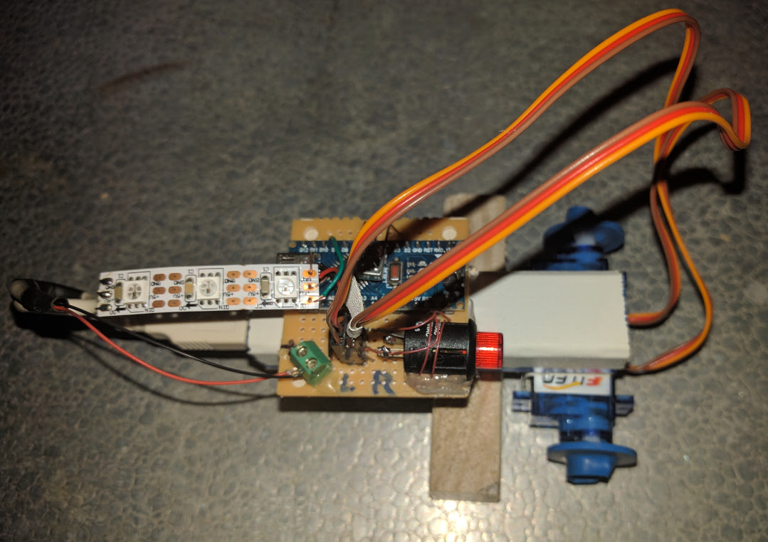
To get started I went with a differential drive but I’ve changed my mind on that. Here’s the differential drive version:
botv2-img_20161120_215020_lr
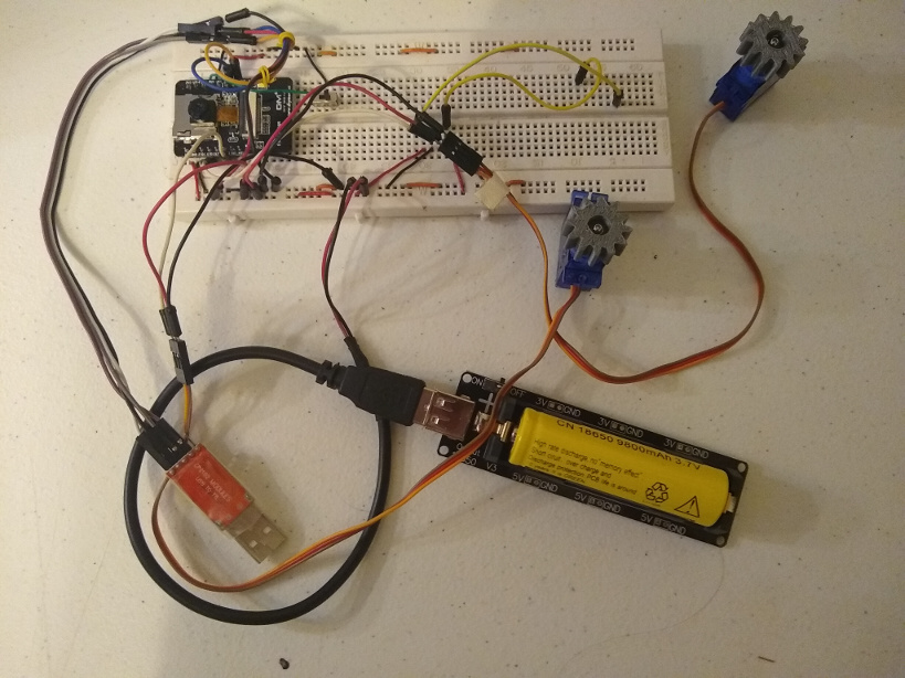
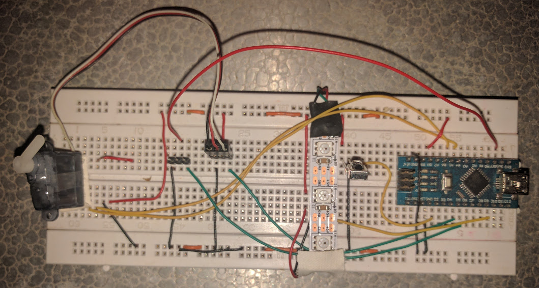
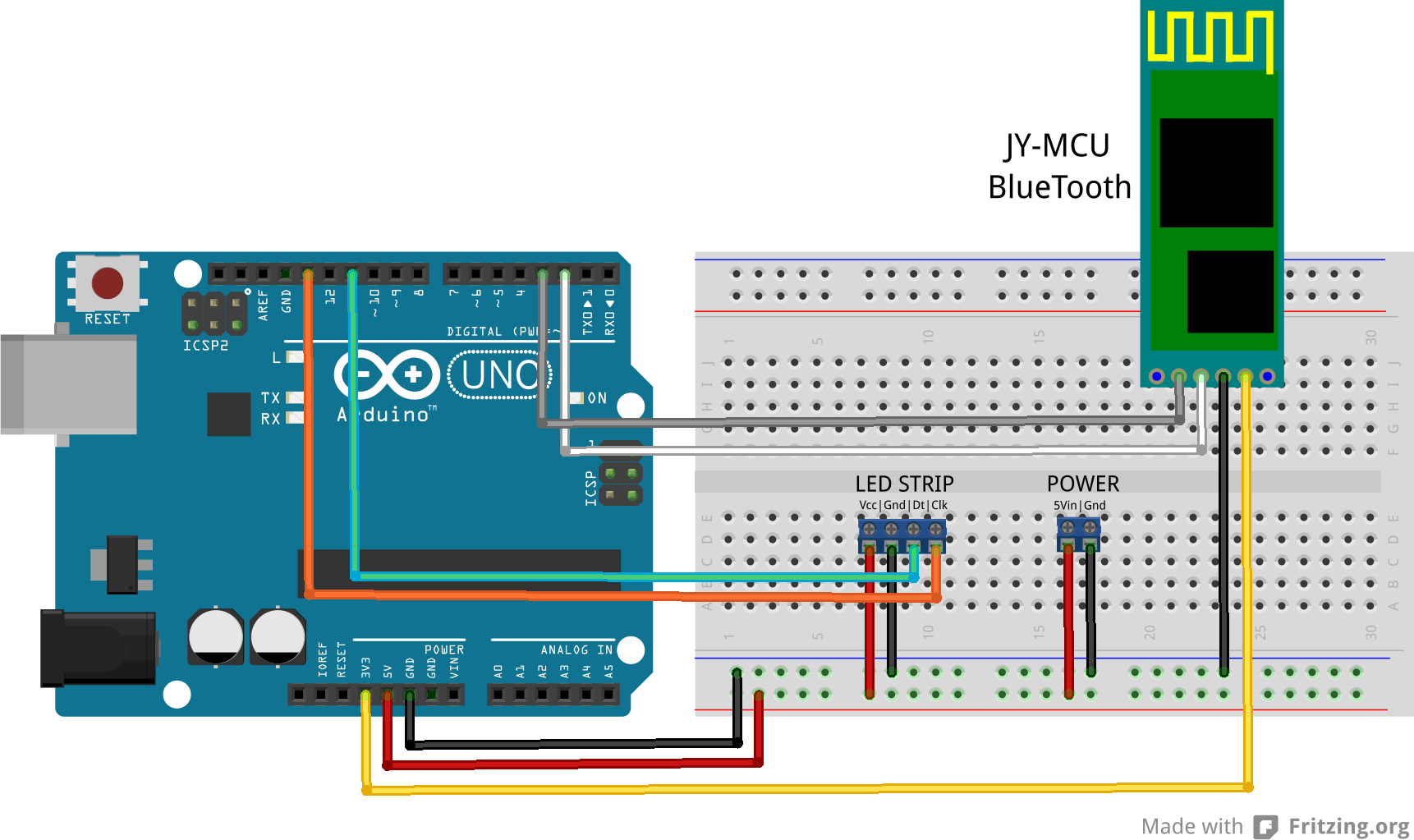
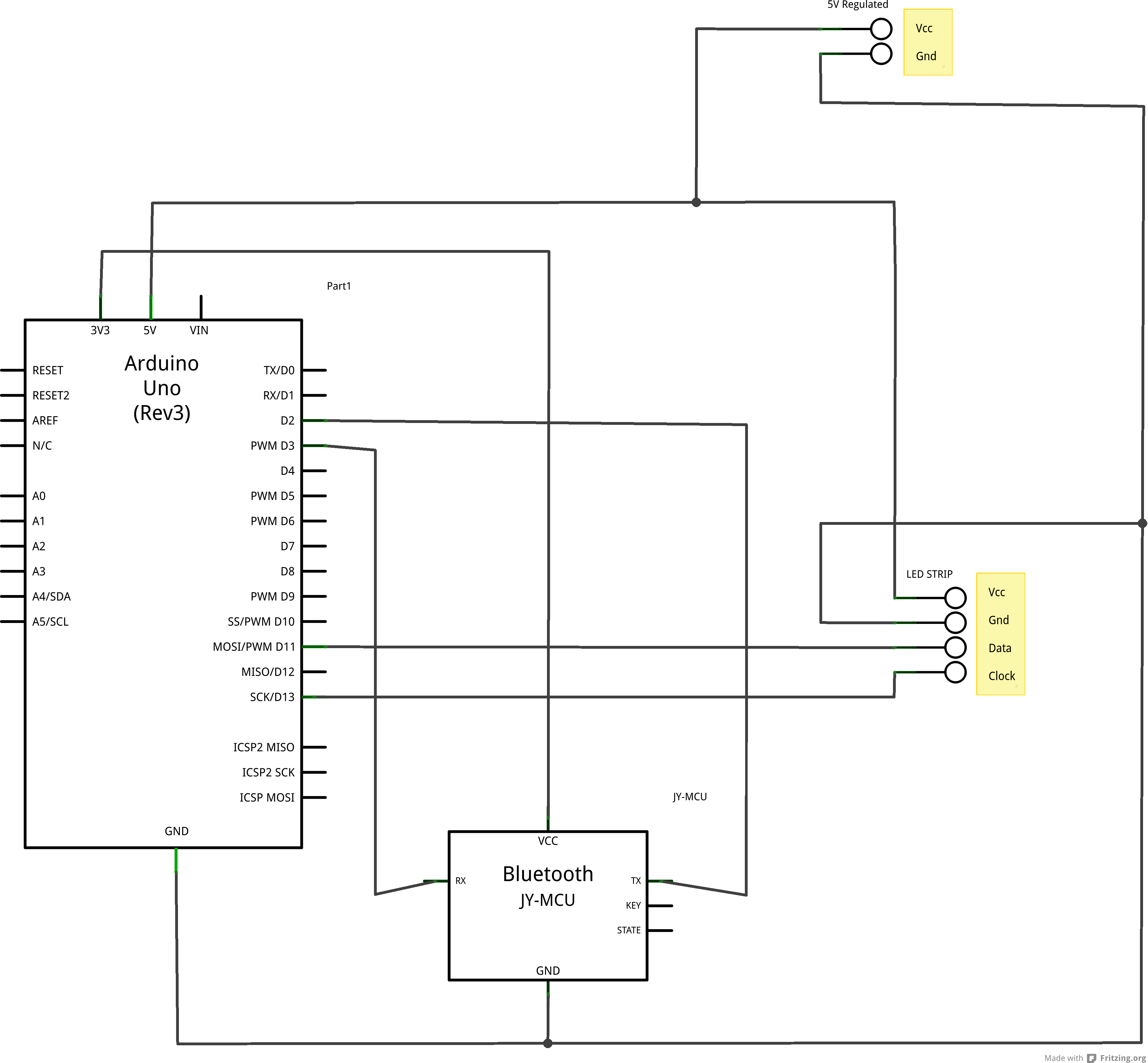
This is basically another iteration of ugbot and tweedle, but actually way simpler. I’ll probably end up calling them Tweedles though, or 790’s, and if you get those references we should hang out. And here’s the breadboard testing rig I made early on to just get all the wiring and code set up before I soldered anything.botv2-img_20161222_211927_lr

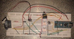
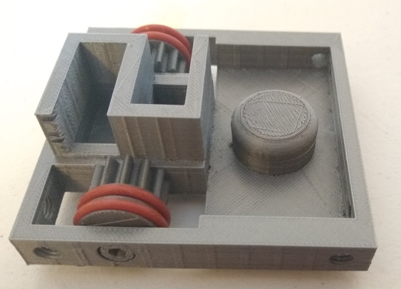
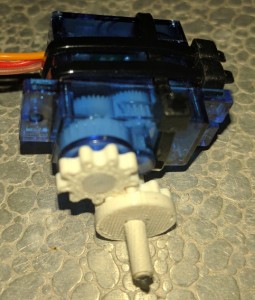
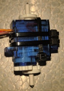
I decided to go with a ‘car drive’ for several reasons. It takes the weight off the servo drive, and I think it’s more efficient to have one drive motor instead of two, plus it means I only need one 360deg servo and those are slightly more expensive or I’d have to mod a regular servo and that’s a pain. I’m still honing the design but I’ve got a basic transmission and steering system made from little 3d printed parts. Here’s the first test print of the transmission. It’s super-simple, gear ratio is 1:1 and it’s strapped on with zip-ties. I was going to glue it but the zip ties magically worked so I think I’m going to plan on using those in the next iteration of the print.

botv2-img_20161218_191906_lr botv2-img_20161218_191924_lr


CONTROL
I decided to use IR control because it’s by far the cheapest as far as parts go, talking about less than a dollar compared to BT, RF or WiFi which can get to several dollars and adds a lot of unnecessary complexity. Though I probably will play with those ESP8266 WiFi modules at some point, I’ve already ordered a couple to mess with since they’re only a couple of bucks.

I don’t really need manual control for the ultimate goal of this, since this is really all an excuse for me to play with computer vision and visual servoing concepts and code, but it makes sense to create a manual controller just for testing.

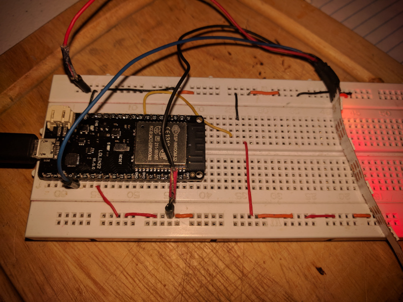
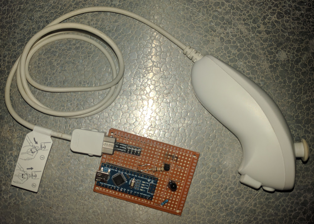
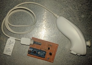
I wasted a lot of time screwing around with a ‘funduino’ board, but it ate up too many pins and one of the buttons never worked so I got frustrated with it. At some point I realized I had a wii nunchuck and a wiichuck adapter already, so I put them to use. The wiichuck is I2C so it only uses 2 data and 2 power pins, way better than the 8 or so pins the funduino required. I wish I’d thought of that before I wasted like $20 on the funduino and an arduino uno to use with it. Here’s the wiichuck IR control rig:

botv2-img_20161222_211845_lr


IR CODE
I had no idea what I was getting into. I’d played with RF and BT modules before, I thought IR control would be simple, and it kind of is, but it’s also kind of a nightmare.

A little backstory on the IR thing- I’ve also been kind of wanting to control flying things via computer vision for a long time- specifically these little cheap IR controlled helicopters. Quads are fun too, but the tiny ones are really hard to control, have terrible battery life, and are more expensive than I’d like. The little IR helicopters are surprisingly easy to fly, cheap, and have decent battery life for a flying thing. Going with IR for the bots was a dual purpose decision, it was cheap for the bots, but it also could lead into controlling the helicopters too.

I started to look into LiRC, but honestly I just got confused, I don’t think that was meant for what I’m trying to do. I slapped and IR LED onto a Raspi and messed around with it awhile, got it to send a few codes, but I just didn’t like it, so I went back to the arduino to actually fire the IR LED. I figured I’d set it up so the PC sends serial commands to the arduino and it fires those off in IR language. I didn’t realize IR language was such a pain in the neck to learn and speak.

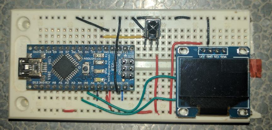
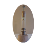
I won’t go through the whole process, a lot of it involves me being an idiot, making stupid assumptions and spending long hours learning how stupid those assumptions were and why they were stupid. This is one of the tools I made to help me stop being stupid. It’s just an IR receiver and an OLED screen I thought I could use to analyze IR codes. It really hasn’t helped that much, but I do like these little OLED screens a lot now. Here’s that thing:botv2-img_20161222_211941_lr

Controlling the bots turned out to be fairly straight-forward. I just used the NEC protocol to send 6 byte chuncks that encode the bots motor states and ‘ID’ (because I expect to be controlling multiple bots with one IR LED), and another byte in case I need it, maybe for RGB LED states or something. It actually wasn’t as straight-forward as all that because the NEC has these repeat code that are just weird and I didn’t know they were happening at first and thought the receiver was junk or something.

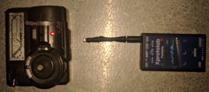
I thought controlling the helicopters would be a matter of pointing the remote at my receiver and reading the codes and figuring out the protocol. That didn’t work. The arduino IR library I was using (IRLib2) had no idea what those codes were. Long story short I finally broke out my little oscilloscope, made a cheap-o IR probe from an IR LED and a broken headset jack. I’m still figuring out the exact protocol these things use but at least now I can see the actual pulses and decode them myself. So far I can get the helicopter to turn its light on and off but even that doesn’t always work. Here’s my trusty gabotronics xprotolab portable with the probe and the helicopter controller- pretty much the best kickstarter thing I’ve backed. This thing is great, and it was like $80 through the campaign.
botv2-img_20161222_212053_lr

WHY NO CODE YET?
Because at the moment it’s not worth posting and I am surprisingly lazy. I’ll post print files and code when there’s anything really worth posting, but if by some bizarre chance you’re working on something similar and give no flips about the state of the code I’d be happy to share.

LATER
I have yet to actually control a robot via computer vision, but that’s part of the long term goal of this. I have played with a little of the code required just to see what I’m getting into. I downloaded VISP Visual Servoing Platform and went through a few tutorials. I realized pretty quick it wasn’t what I needed, or it was a lot more than I needed. It also meant I’d be coding in C++ and I was okay with that but it wasn’t my preference. I realized most of the functions I needed where actually OpenCV so I just went to that, and I can use python, which makes my life much easier.

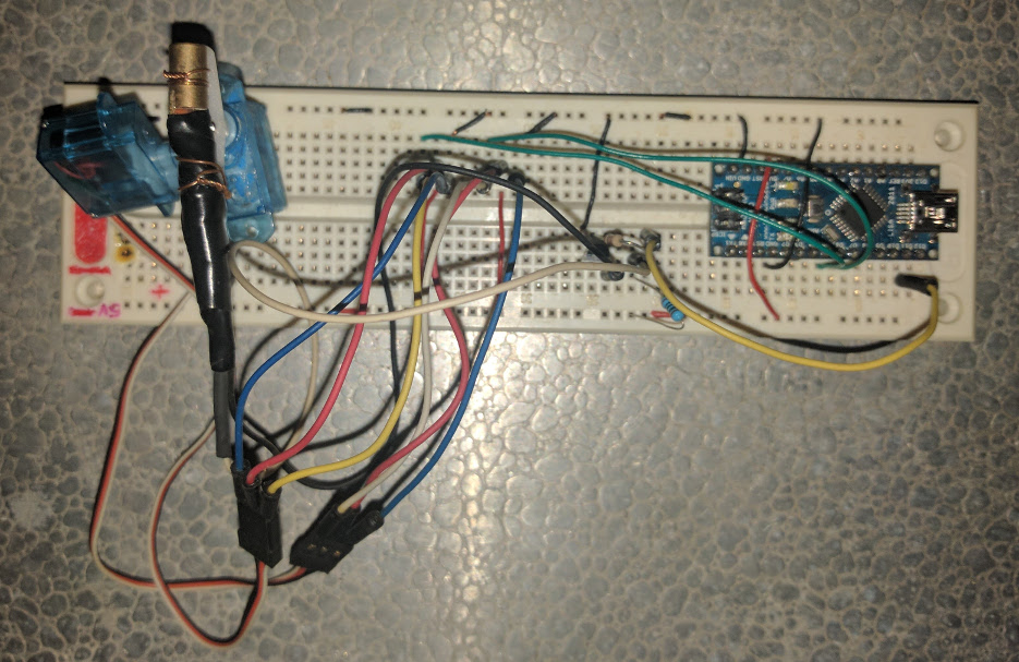
Since I know I’ve got a lot of work to do on the bots I thought I’d make an even simpler platform to test object tracking. So I put together this little rig that has 2 servos with a laser diode slapped on it so I can just point it and a camera at a wall and start tracking the movements of the laser and control it with visual feedback. Here’s that little rig:botv2-img_20161222_215613_lr

This is really nothing so far, I’ve just been randomly poking at this idea for a few months and decided I should post something to try to get back in the habit of posting stuff I work on. I would be nowhere with my arduino stuff if it weren’t for other people’s little blogs and sites so I figure I’m obligated to offer the same to some other random shmuck trying to fudge their way through an idea that’s really way over their head but they dive in anyway. Here’s to you, shmuck.

WAIT, WHAT?
Yeah- I know. I’m not really sure either.

I’ll post more on this project as it evolves, but it is just kind of an cloudy vision of an idea so don’t hold your breath for anything spectacular. I think the old progranimals and lightning stuff was actually cooler and I should probably be developing that stuff more, but this is what I feel like doing now so I am.

Jun 142015
 

So here’s something I should have posted quite awhile ago. This is a ‘breakout board’ I made for controlling LED strips with Arduino over bluetooth or USB.

PCB

It’s a little PCB for an Arduino nano, bluetooth chip, and (3) 4-pin terminal blocks with PWR-GND-SN-CK, and a 2-pin block for PWR-GND input. It can be used with 3 or 4 pin LED strips, or anything really, servos, sensors, whatever. I designed the PCB using Fritzing and had it printed through OSH Park. If you’re interested in one let me know via the funkboxing contact form. I’ll offer just the bare board or a pre-soldered and tested version with a nano, bluetooth chip, and terminal blocks, or any variation thereof. I can’t really come up with a price that makes sense, so if you tell me what you’re planning on using it for and I think it’s cool I’ll probably give it to you pretty much at-cost.

And here’s an LED array I made with it.

Array

It uses (64) WS2811 LED’s in an 8×8 array, an Arduino Nano, bluetooth chip, and a USB battery pack. It’s a double-decker sandwich of (3) 1/2″ thick acrylic plates so the whole rig is excessively large and heavy, but I kind of meant for it to be that way. I wanted something as a little testbed for 2D effects, of which I’ve only made a few so far. I’ll post the 2D array code at some point, but I should clean it up and make sure it works with the newest FastSPI library first.

Jun 142015
 

***EDIT*** Now available on Etsy – https://www.etsy.com/shop/funkboxing

So here’s a redesign of the Levitube things I made awhile back. It’s essentially the same, just slightly more aesthetically pleasing with the wooden base and cork stopper and spade thumb-screw. That link above is super old and I don’t feel like updating a super old html page, if you click it just ignore the parts that contradict this post, like the part saying they’re no longer for sale- They ARE for sale again. That’s probably unnecessarily confusing… but anyway. Look! Here’s the new design!

LeviTube

It’s an acrylic tube with a little magnet that levitates between two bismuth pellets. Basically it’s thing to stare at occasionally. I’ve also had fun making it spin and shining a laser on it so it flashes the laser around, I’m easily entertained like that. I’m sure there are practical uses for the effect, but the levitubes are really only good for the staring bit.

It’s either an ‘educational demonstration’ device or ‘desk-toy’ thing. When people ask you about it you can tell them about the principle of diamagnetism and they’ll think you’re all smart, or more likely they’ll just think you’re tragically nerdy. Optionally, you could tell them you’re doing it with your mind or you bought it at a shop in Diagon Alley and it’s enchanted, your call.

If you want one, let me know via the funkboxing contact form. I’m going to ask you to send me $30 via Paypal and that’ll include shipping within the U.S. If you live somewhere else, just ask and I’ll find out what the shipping is to there. If you live in Iceland or the Netherlands I might ask if I can come stay with you for awhile because I’d really like to go to those places but I don’t have a lot of money. I also might need to borrow some warm clothes because I don’t have anything for cold climates, I’m from the south.

I’ve only got about a half-dozen ready to go at the moment but I can make more, it’ll just take a little while longer to get one to you. They also include a cool stamp with the funkboxing logo on the bottom of the base so you can remember where you got it.

-Me


*The dime in the image is for scale, it’s not included. I guess if you ask me I’d send you a dime too, but you can probably source one locally. It’s not a rebate thing. If you absolutely insist I’ll just give you 10 cents off the price instead, but I’d probably make fun of you for being so insistent over 10 cents. I’ll give you a whole dollar off if you read my ‘Hello, World’ short story and tell me what you think since I really spent some time on that and I don’t think anybody’s read it yet. If you’re Limor Fried and you request one I’ll send you a free one since you’re so totally awesome and I love Adafruit Industries.


Nov 102013
 

[EDIT] Here is a link to an update of these effects made by Stefan Mayer designed to work with the OctoWS2811 LED Library. Thanks a lot Stefan, great work!

[EDIT] I’m planning to clean up the Android control app source and put it on github, but in the meantime here’s the code.

[EDIT] If you end up using this code for a project please send me a link/pics/video! I love seeing what people do with this! If you like I’ll post a link to your project on the FastSPI FX – User Coolness post. Also make sure to thank Daniel Garcia (the genius dev of the FastSPI library) on the G+ FastSPI Community.

Here is an update to the Arduino FastSPI2 FX demo code (v0.51). I’m also introducing an Android Bluetooth Control App and a Chrome Extension.


I’ll continue to work on improving these programs but I think I have them to a point where it might be useful to some people- so here they are!

Here is the Arduino Sketch (v0.51)

Here is the Android App on the Google Play Store (v0.1a)

Here is the Chrome LED Controller Extension (v0.1)

— — — SETUP / NOTES — — —

ARDUINO:
– This version uses the Software Serial library and FastSPI2 library. Also the default serial speed is now 57600.
– The following is a breadboard layout and schematic for setting up a JY-MCU Bluetooth chip with an Arduino (Duemilenove or Nano) to drive a strip of addressable LEDs. This should work with any LED strip that is supported by FastSPI2 RC4 and later.
ArduinoBTLEDSimple_011_breadboard_bbArduinoBTLEDSimple_007_schematic_schem

ANDROID APP:
– To control LED strips via the Android app you’ll have to pair the JY-MCU module with your smartphone/tablet in the Bluetooth/Wireless settings. The PIN for these modules is usually 1234.

CHROME EXTENSION:
– To load the extension, unrar the file to a directory. Then in Chrome go to Settings>Extensions>Load Unpacked Extension. Then select the directory. Then you can launch it from there.
– This extension has been tested on Ubuntu 12.04 and WindowsXP. For Windows you’ll have to install the USB Serial drivers, but the automatic driver search seems to work fine for this.

— — —

If you find this really useful, please consider donating a little to the cause. Thanks!
[paypal-donation reference=”FastSPI2 LED FX – Android/Chrome”]

I’m also grateful for bitcoin donations to: 1K5Yy77ejes2FZrHBG5fns3QAicnwZcduq


Oct 152013
 

I had a little trouble finding references to how to setup multiple strips with FastSPI2, so I thought I’d post this.

You just use an offset value like in this example:

LEDS.addLeds<WS2801, 7, 9,   RGB>(leds, 43);       //<---Strip1 - WS2801 - 43 LEDs
LEDS.addLeds<WS2801, 11, 13, RGB>(leds, 43, 12);   //<---Strip2 - WS2801 - 12 LEDs
LEDS.addLeds<WS2811, 5,      GRB>(leds, 55, 16);   //<---Strip3 - WS2811 - 16 LEDs

In the additional strips the first integer passed becomes the offset value and the second is the number of LEDs in the strip.

LEDS.addLeds<STRIP, CLK_PIN, DATA_PIN, RGB_ORDER>(ARRAY, OFFSET, LED_COUNT);