UPDATE: Pretty much resolved the stability issues with the ESP32CAM and posted it on github – https://github.com/funkboxing/espcreep
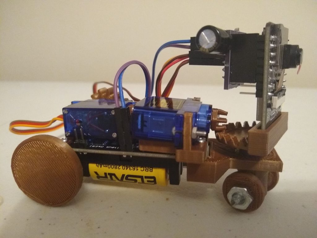
Here is the first semi-functional build of a bot type thing I’ve been working on. I’m calling it ESP Creep, because it’s ESP based and it kind of creeps.
It was made to have a minimum part count and be simple to assemble and control. I’d like these to be available for anyone who wants an extremely inexpensive robotic camera platform. I always envisioned some kind of desktop multi-bot ‘soccer’ platform to help learn and play with vision control systems and such, but there weren’t any cheap-o bots that really fit the bill. This isn’t ready for much except more development, but it does most of what I intend it to do, albeit very poorly, so I figured I’d share.
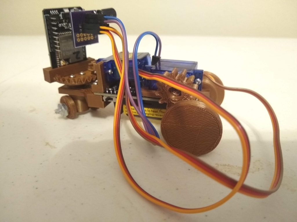
Here are a couple of obligatory glamour shots of the bot. Just look at those unnecessarily long, flowing servo leads… majestic.
These are the parts involved, sans 3d printed parts and a half-dozen 8mm m2 screws.
~ESP32CAM
~SG90 Hobby Servo (Angle)
~SG90 Hobby Servo (Continuous Rotation)
~16340 Battery Module and battery
~1000uf (6.3v) Electrolytic Capacitor
~Breakout PCB and Connectors.
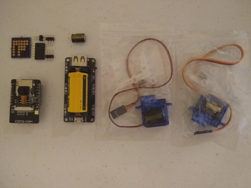
The PCB breakout is the only custom part, and it’s not strictly necessary, just very convenient.
I chose not to do the traditional differential drive. I’m not entirely clear on why I didn’t want to, but I’ve rationalized it with a few apparent advantages. One it’s just easier to handle control wise. There’s no need for ‘mixing’ turn and throttle variables into the motor values. This just makes it +/- for drive, and +/- for turn. Also you don’t have to calibrate motor speeds to make the thing go straight. Mounting the motors for differential drive seemed to make the bot footprint larger, or wider at least. Also I like that it makes steering pan the camera. And I can’t always find continuous rotation motors and I hate modifying angle servos.
Obviously the next step in the 3d design is to get some friction happening on the wheels, and tighten up the wiring situation.
The big problem is the ESP32CAM software. It serves up the camera and parses UDP packets to command the servos. You can see in the video at the end the connection drops. It does that about 30 seconds after you connect. Sometimes I can reconnect right after, but sometimes I need to reboot the ESP. I know the ESP32CAM can be fairly stable because I have several running esphome on hass.io. But I cannot get these things to stay connected with Arduino based code. Some of it might be the motor power demands, the ESP’s are a little finicky with power, but it’s not consistent with motor power, it drops when it’s just sitting there. I added a big honking cap that I think resolves any brownouts but I don’t think the ESP is rebooting because I can still ping it right after it drops the camera connection. I can’t get any error output when it’s connected to serial that gives me any clue what’s happening. But I’ll keep working on it, I’d love some help if anyone ESP savvy has any ideas.
Here are the files. These are not really well organized. It’s everything you’d need to recreate this bot, but it’d take a pretty handy person to get it all working. I would love it if another DIY nerd wanted to jump into this, especially the ESP32CAM arduino sketch. Fair warning this is terrible code and I express my frustration in comments and variable names. Also I can’t find the stencil files for the PCB right now, but I got it made by OSHPark so they’re still up there. Eventually I’ll get more and maybe sell them in kits or something, but if anyone wants them just let me know, I think I can get the files from OSH. Also it’s just breaking out power and data for the servos so anyone could reproduce it.
Contains:
~Blender 3d File
~Arduino Sketch
~Python File (keyboard control)