Jun 012020
 

I’ve learned a lot about acetoxy silicone, but most of what I’ve learned is I have no idea what’s going on and I just try to make it do something resembling what I want, but not be too picky. I haven’t found much information online about using silicone this way, so I figured I’d make some notes about it.

DIFFUSION
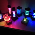
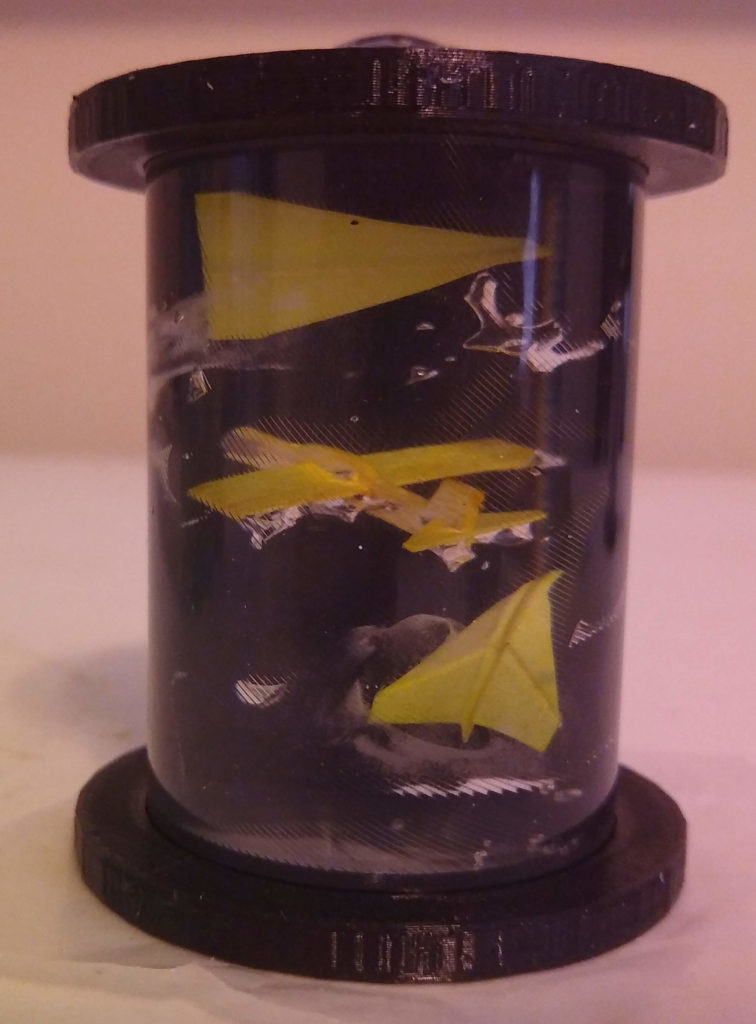
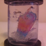
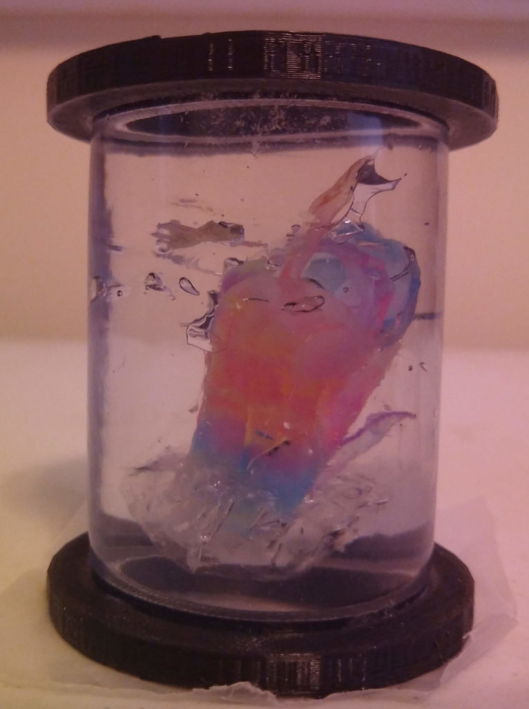
Silicone make a uniquely perfect transparent diffusion. It somehow transmits and bounces enough light that a few LEDs can fill up a volume with light, and show a little of the ‘beam’, but the volume remains transparent. I’m not sure what makes it so perfect, but I’ve tried several other clear fluids and this silicone does this kind of diffusion better than anything I’ve tried. And so far this DAP Ultraclear acetoxy cure silicone is the only kind that’s water clear and still workable. I found some loctite adhesive that’s as clear, but it’s a different chemistry and hardens weirdly and just doesn’t work, also it has a slightly yellowish tint. I guess epoxy resin might have a similar effect with light, but it’s expensive and I think UV messes with that over time. For whatever reason clear silicone just makes a beautiful substrate for lighting little miniature scenes.

CURING
As I understand it there’s something called ‘cross-linking’ going on where H20 molecules are exchanged from the air with acetic acid in the silicone. That process is what solidifies the silicone. I only have the vaguest idea what that means chemically.

When you lay in the silicone as thick as the balsa tubes, it seems to ‘self-heal’ any interfaces between silicone layers. Very small bubbles in ridges between ‘beads’ tend to go away quickly. Bubbles up to about 3mm in diameter seem to go away within about a week.

I’m not sure these tubes will every fully cure. So far the oldest tube I have is about 4 months, and it’s still a bit malleable in the middle. You can push the whole scene up or down a few mm by pressing the ends. Pretty sure it’s just forming a ‘plug’ of cured silicone that eventually gets large enough to stop any deeper curing. But it does keep going for a while. I’ve found if I seal the ends flush, within about a month I’ll need to ‘top off’ the tube because it’s shrunk about 4-5mm in. I’ve started adding a layer of cling wrap once they’re in the lights but I’m not sure if they’ll just slowly shrink for years and end up looking crazy with big domes pulled in from either end.

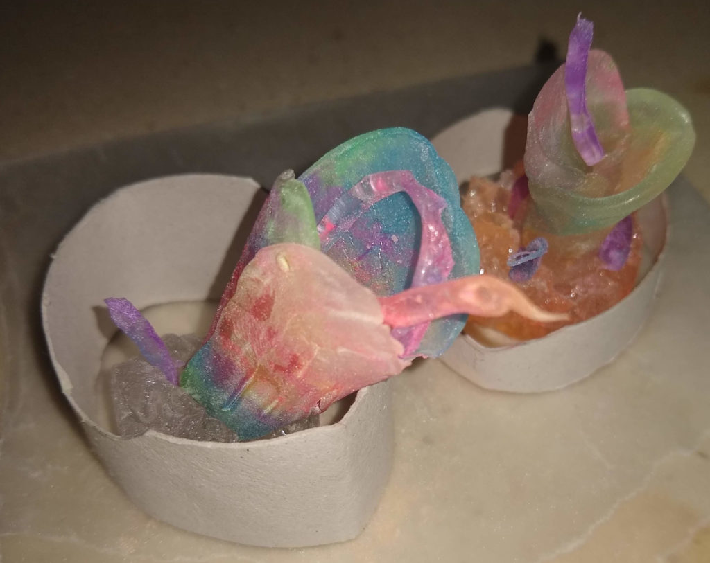
Pre-cured silcone slabs with powder and glitter seem to blend into fresh silicone over time. The interface disappears within a day and you can only see the inclusions. I’ve pulled dioramas apart after about a month and it seems like the pre-cured silicone softens considerably. When pulling apart the silicone it has a uniform viscosity in the center, even in places where the pre-cured silicone layers were previously very solid.

I’ve had no big breakthroughs in speeding up the curing process. I haven’t been very scientific with control groups, but I have some observations:

MOVING AIR – I just put a fan on it. Seems like that has to do something. If you leave curing silicone in a closed space it starts to smell strongly of vinegar, so makes sense clearing that out with a fan might move things along.
MOISTURE – I’ve tried submersion, vapor, and mist. Submersion does nothing, almost seems like it prevents curing somewhat. Vapor and mist seem to help harden up the outer layers, but I don’t know if that’s actually bad for curing deeper within the silicone. I do notice that if you put an older tube in a closed space with a mister, it starts to smell more strongly of vinegar than in a dry space. So maybe it’s doing something and I’m just too impatient.
HEAT – I left them in my car on a hot day, submerged in nearly boiling water, and used a USB heater to keep them about 60C for a day. I destroyed about 3 tubes in the process. The PLA gets soft about 80C and things get weird. I might try to keep it closer to 40C for a day or two, but so far seems like heat causes more problems than it’s worth.
UVC – I got a 8W UVC tube light. Made a little black out box and stuck it in with a tube. It does something because you smell burnt rubber as soon as you turn it on, but after a couple of days it didn’t seem to cure any faster and the PLA was starting to fade. I’m guessing the UVC only penetrates a little bit and just cooks the silicone on the top and does nothing deeper in. Anyway I knew it was probably a bad idea, but I had the light and couldn’t not try it.
PRESSURE – I have a USB food vaccum pump that I was hoping would help get some bubbles out, but it doesn’t. I would like to see if possibly raising the ambient pressure a bit could help speed the curing process. Ideally a small chamber capable of 2-3atm with humidity and heat control, but I live in an apartment and my kitchen is insane enough as it is so that’ll have to wait.

SOLDER CLOUD
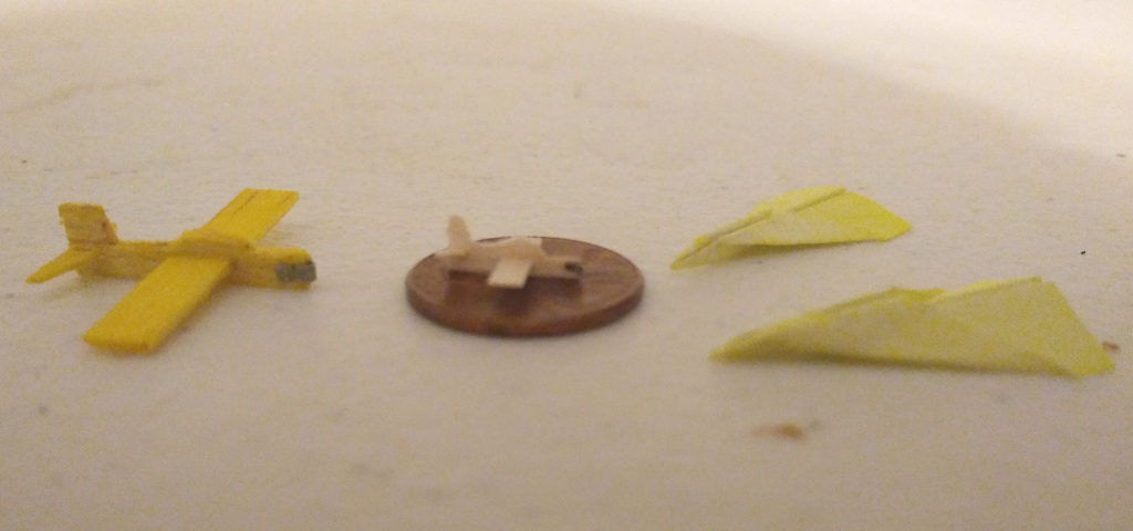
The ‘nose weight’ on the balsa planes seems to create a yellowish cloud over time. It takes months and isn’t very noticable, but it’s very consistent. It expands out perfectly radially around the nose weight. Something is leeching out into the silicone, possibly tin or the rosin. You can only really tell with the LEDs off and held up to a light, so it’s not a big deal, but I may try to find a different material for the nose weights.

WATER
Keeping your fingers wet allows you to handle fresh silicone to some degree. It’s useful for smoothing and patting layers into each other. But it does seem to introduce a cloudyness in thick silicone. You can only really use water on the outer layers.

G-FORCE
I figured I could move things around in the silicone with a kind of centerfuge so I made a kind of sling. As a test I used a 6″ section of 1″OD tube filled with fresh silicone. I put a couple of bismuth beads at the top. I figured if anything would move in the dense silicone it would have to be pretty dense. Very rough calculations of the radius and rpm spinning it by hand I got about 9G’s and kept that up for about 20m. I manager to move the beads all the way through, but they jammed up against the tube wall as they went down. I figured there’s no way to use that so that’s about as far as that whole thing went. I’m sure a more precise and powerful centerfuge could do better, but not sure if there’s a point.

CLING WRAP
Counterintuitively, cling wrap is the best material I’ve found for kind of ‘molding’ silicone. I tried aluminum foil and wax paper. Foil tears when you try to get it off, and wap paper leaves a residue even if it doesn’t tear. I also tried thicker sheets of plastic and the silicone tears when pulling it up. Cling wrap is flexible and strechable enough to remove from silicone if you let it shrink onto it. It doesn’t work as well if you ‘pre-strech’ the cling wrap like a canvas. It also works okay on fresh silicone if you peel it back very quickly. It will stick, but it leaves a fairly smooth interface.

GLYCERINE
I need to do some more testing with this as a release agent and such. I also wonder if a a ‘vape’ device generating glycerine vapor could help speed up the curing process, but haven’t figured out how to test that without things getting very messy.

SILICONE MOLDS
I ordered some of those molds they use for epoxy resin, but they never came in. Still not sure if these would even work or if the silicone would bond too well. They do make some cool shapes though so I may still give these a shot.

OTHER STUFF
I think I’ve tried injecting pretty much every household chemical I have to see what everything does and looks like when injected in clear silicone. Most stuff just looks like what you’d expect. vegetable oil, bleach, various glues, other silicones, detergent, goo-gone, acetone, and my favorite experiment- alka-seltzer. Nothing really did anything that interesting, execpt alka-seltzer- I ground up a couple of tabs and cured it in a tube for a few weeks, then injected water into it. It did about what you’d expect- just slowly pooed out the silicone. It was unimpressive, but worth mentioning I guess.

May 142020
 

UPDATE: Pretty much resolved the stability issues with the ESP32CAM and posted it on github – https://github.com/funkboxing/espcreep

Here is the first semi-functional build of a bot type thing I’ve been working on. I’m calling it ESP Creep, because it’s ESP based and it kind of creeps.

ESP Creep demonstrating how poorly wheeled vehicles perform without friction.

It was made to have a minimum part count and be simple to assemble and control. I’d like these to be available for anyone who wants an extremely inexpensive robotic camera platform. I always envisioned some kind of desktop multi-bot ‘soccer’ platform to help learn and play with vision control systems and such, but there weren’t any cheap-o bots that really fit the bill. This isn’t ready for much except more development, but it does most of what I intend it to do, albeit very poorly, so I figured I’d share.

Here are a couple of obligatory glamour shots of the bot. Just look at those unnecessarily long, flowing servo leads… majestic.

These are the parts involved, sans 3d printed parts and a half-dozen 8mm m2 screws.

~ESP32CAM
~SG90 Hobby Servo (Angle)
~SG90 Hobby Servo (Continuous Rotation)
~16340 Battery Module and battery
~1000uf (6.3v) Electrolytic Capacitor
~Breakout PCB and Connectors.

The PCB breakout is the only custom part, and it’s not strictly necessary, just very convenient.

I chose not to do the traditional differential drive. I’m not entirely clear on why I didn’t want to, but I’ve rationalized it with a few apparent advantages. One it’s just easier to handle control wise. There’s no need for ‘mixing’ turn and throttle variables into the motor values. This just makes it +/- for drive, and +/- for turn. Also you don’t have to calibrate motor speeds to make the thing go straight. Mounting the motors for differential drive seemed to make the bot footprint larger, or wider at least. Also I like that it makes steering pan the camera. And I can’t always find continuous rotation motors and I hate modifying angle servos.

Obviously the next step in the 3d design is to get some friction happening on the wheels, and tighten up the wiring situation.

The big problem is the ESP32CAM software. It serves up the camera and parses UDP packets to command the servos. You can see in the video at the end the connection drops. It does that about 30 seconds after you connect. Sometimes I can reconnect right after, but sometimes I need to reboot the ESP. I know the ESP32CAM can be fairly stable because I have several running esphome on hass.io. But I cannot get these things to stay connected with Arduino based code. Some of it might be the motor power demands, the ESP’s are a little finicky with power, but it’s not consistent with motor power, it drops when it’s just sitting there. I added a big honking cap that I think resolves any brownouts but I don’t think the ESP is rebooting because I can still ping it right after it drops the camera connection. I can’t get any error output when it’s connected to serial that gives me any clue what’s happening. But I’ll keep working on it, I’d love some help if anyone ESP savvy has any ideas.

Here are the files. These are not really well organized. It’s everything you’d need to recreate this bot, but it’d take a pretty handy person to get it all working. I would love it if another DIY nerd wanted to jump into this, especially the ESP32CAM arduino sketch. Fair warning this is terrible code and I express my frustration in comments and variable names. Also I can’t find the stencil files for the PCB right now, but I got it made by OSHPark so they’re still up there. Eventually I’ll get more and maybe sell them in kits or something, but if anyone wants them just let me know, I think I can get the files from OSH. Also it’s just breaking out power and data for the servos so anyone could reproduce it.

Contains:
~Blender 3d File
~Arduino Sketch
~Python File (keyboard control)

May 112020
 

No wise man ever said “You can’t start trying to make warp coil lights and get caught up in a whole other thing with the stuff you started making the warp coil lights with and then not eventually get back to warp coil lights.”

And you know what? They’re right- because nobody should ever say that, and that’s exactly what I did.

THERE ARE FOUR LIGHTS!!! on the right, and three on the left.

This is another warp coil light, this time with WLED but I haven’t added the warp effect loop yet, this is just WLED onboard effects. If I haven’t mentioned it enough- WLED rocks the\my casbah and\or world. The video shows the original warp coil light on the left and the new warp coil light on the right.

I wanted to take a video with the new warp light running the ‘warp’ loop, but somehow it became a familiy reunion of all the 3/8″ tube lights. The shotlight build hasn’t gotten much love lately, not sure if I’m going to get back to it, bit of a lark, but it does look cool next to it’s cousins. #TUBELIFE

Interestingly, the old tubes seems to do a better job of transmitting the light around the curve and I’m not sure why. The old light and the silicone is only a few months older than the new one, but the actual vinyl tubes I used for that light were ones I’ve had for years. I think that roll of tubing had been sitting in my parts bin for a decade. I do notice the older vinyl has a slightly yellowish tint. I’m not sure if that’s from the factory or from sitting and accumulating layers of tobacco smoke. Whatever it is, I wish I could duplicate it. You can almost tell in the video that the middle of the new light doesn’t get quite as much light, but the old one is pretty even throughout.

Anyway- the new one has four coils instead of three because THERE ARE FOUR LIGHTS!!!

Apr 292020
 

Today we pay tribute to a project that I never posted when it worked, but should have, because now it’s too late.

I downloaded the STLs for this mini (MAC) moving head light about 4 years ago and printed them immediately.

Then for the next 4 years I made several half-hearted attempts to assemble the thing and get it running with an arduino sketch. At some point I had it together with 9g hobby servos, then I decided I wanted metal gear servos so I swapped them out. Getting the tilt servo and LED wired in through the head is a pain, and I think the design puts a lot of stress on the tilt servo that even a MG servo can’t handle indefinitely.

I used a Lolin32 to drive the servos and LEDs, and at one point I got a YAML config that let me drive the servos and LED via Home Assistant. But I never really used it for anything, every time I got it working with something I’d pack it back up after a couple of days because it wasn’t very fun to control.

But then I finally got Art-Net working on other ESPs and QLC+ provided the kind of control I wanted. So I got a pretty crappy sketch going that was able to execute Art-Net commands for the LEDs and servos. I watched it draw a figure 8 pattern on my ceiling for about a half hour.

So yay! I finally found a place for my little MAC light! I’ll just let it sit in the corner and set up some little light show functions for alerts and that will be cool.

Hey- what’s that’s smell? Did something short out? idk… oh well, I’ll find it when it catches fire or something doesn’t work any more.

Hey… the little MAC light is at a weird angle, thought I had it default to centered…

Oh, the tilt commands aren’t doing anything, not even a sound from the motor. I wonder if the servo connector came loose- nope it’s on there. I guess I have to pull it apart.

Hmmm… servo’s a little warm, that’s not great. Do you remember how the servo horn is secured in there? Did I glue it? I don’t think so… it’s just stuck in there probably, I just need to pry it up a litt… SNAP… oh it was screwed in- and the infill density on that part was super low so… yeah, that’s totally broken now… and oh, the tilt motor is utterly frozen, can’t even turn it with pliers.

So that’s how it happened. I could reprint the part but I won’t, I like pan\tilt lights but this particular design maximizes the MAC light look but probably isn’t the best design for functionality.

But I spent a lot of time messing with this thing and looks like I’ll never get to post it in action so here’s a rememberance.

Apr 282020
 

My recent experience with WLED has made me think all these years coding out FX loops were a monumental waste of time. I should have just waited for WLED to exist. Not really, I learned a lot, but WLED is seriously the benevolent overlord of LED control code, and of course it includes the godfather of LED code- FastLED. I know I can gush over awesome open source projects, but WLED is a transcendental gift to reality. I have been looking for and vaguely pretending to plan to code something like this since I started playing with LEDs, but this is far beyond my abilities as a coder, or a human being. Anyway- WLED is the alpha and the omega for LED projects. So I’ve been smartening up a couple of dumb lights with it and smiling and clapping at some for the first time in a long while.

Here’s a video of a few lights running WLED, but it doesn’t demonstrate a fraction of the control options or effects.

Trusty Old 8×8 Matrix, ‘hextube’ (SEVEN), and a balsa tube

I’m still really digging the hextube configuration. I don’t really plan on making more of them because it’s kind of quirky and I don’t think many people would be into it, but I really dig it but I haven’t been able to figure out a good FX loop for it, so I gave it an ESP8266 brain and took it to WLED university. Now I can control it with QLC+ via E1.31, but the onboard WLED FX are pretty wicked too. WLED lets me define different sections of the strip to do different FX, so I defined ‘segments’ for the outer tube LEDs, the area LEDs, and the inner tube LEDs and set them all to slightly different loops and pallettes. The video shows ‘wipe’ running on the outer and area LEDs but with different timing and opposite directions, and ‘plasma’ running on the inner tube LEDs. I think it looks pretty cool. I don’t even want to start parsing out how I would recreate this loop in an Arduino function, and now I don’t have to- and I might never again.

The video also shows an 8×8 LED matrix I built a while back using WS2812B strips, the bluetooth breakout board, and about 20 lbs of acrylic. I have no idea why I thought 3 sheets of 1/2″ acrylic were appropriate for this, but the thing is solid. It’s been running the fire effect 24/7 for at least the past 5 years. It was pretty trivial to swap out the Nano board for an ESP01. I also added a capacitor across the +/- just because I’ve learned you should do that for larger displays. The display is just running ‘plasma’ on very low brightness to let the hextube shine.

And there’s an obligatory balsa tube because it’s running WLED too and balsa tubes are just my jam now. I modified the WLED source to add the little crossfade effect loop for the balsa tubes so it starts up running that and it’s selectable and dimmable in the webUI. I’m having a little trouble figuring out how to handle the WS2811 PCB LEDs with WLED. I want them to stay off for regular onboard FX and only use them in the custom FX, but if I put them in a different segment they don’t work in the custom FX either. It’s not a huge deal but I’d like to get it straight.

I would like to take this opportunity to give the hextube a more fitting moniker since I’ve called several tests and builds ‘hextube’. It’s become a bit of a ‘my grandfathers axe’ situation with the parts but I think it’s going to stay what it is now. So I’m going to start calling this particular build SEVEN.

Apr 252020
 

Information page for the lights available in the funkboxing Etsy shop.

STYLES
BLOOM – Looks kind of like a weird underwater flower with fluorescent stems.
FLAME – A bubbly flame sort of thing, usually orange-reddish.
CLOUD – Like if you could drill a core sample from a cloud or something, but more colorful.
GUMBO – Whatever looks cool in a tube but isn’t one of the other styles.
SPACE – Scenes of whatever looks cool in a larger tube made from a fresnel lens sheet.

PARTS\MATERIALS
MicroUSB ATTINY85 Board, WS2812B LEDs (RGB and UV), WS2811 PCB with Discrete LEDS, Vinyl tubing, Silicone, Fluorescent\Glow-in-the-dark pigments.

DISCLAIMERS
~There’s a 10 second delay after you plug them in before the lights turn on. This is due to to the controller board being programmable and just is what it is because I want people to be able to reprogram them if they want. See ‘Hackability’ if you’re interested.
~These lights are not perfectly manufactured. They’re built entirely by one guy with a poorly calibrated 3d printer in the kitchen of a one bedroom apartment, but they should do what they’re made to do, which is light up and look kind of pretty.
~Don’t handle them too aggressively. They’re sturdy enough to survive light knocks, but they’re just display lights. The tubes are not completely rigid so you can squish them hard enough to destroy the scene if you try, but don’t try you should be fine. For best results just plug and stare.
~I guess they could catch fire, but most things could. These run at 5V and pull less than 50ma but they are made of electricity and rubber and that combination has some flammable potential so I feel I should mention it.
~Don’t consume them or let children or pets consume them. They’re probably toxic at some level and it just can’t be good for you. They look way better than they taste. Also these have zero considerations for children or pets so just keep them away entirely.
~I’ve hidden a false but very convincing secret of the universe in every 42nd light. The message is encoded in the LED’s PWM so it’ll become embedded in your subconscious the instant you turn on the light. Try not to fall for my cosmic lies.

PROCESS
At some point I’ll put more effort into documenting the process of working with silicone because it is pretty interesting and I haven’t found references to anyone else doing this kind of thing with it. I got some inspiration from people who work with clear resins, but silicone has a lot of different properties. My initial choice of silicone was by circumstance, it’s just cheap and available, but by now I appreciate some properties that make it a very unique substrate. I also found some information from people who had experimented with silicone to create homemade casting molds that turned out to be pretty useful.

This all started with the desire to make a kind of ‘warp coil‘ light. I found clear silicone worked well as a tube filler to make little ‘wave guide diffusers‘. Then at some point I had the notion to inject highlighter fluid into it for the fluorescent effect. A few dozen bizarre notions and experiments later I’d figured out several materials and techniques that looked cool enough to put in little lights.

The electronics were pretty simple since I’ve been working with Arduinos and LEDs for about a decade, though I did have to do some thinking and tinkering. I’ve been going back to the Arduino Nano for years. It’s my default for any non-wifi project, but I wanted USBMicro and the Nano is actually way overpowered just to drive 2-10 LEDs. I found the old digispark ATTINY85 board I got from their kickstarter (the USB-A version) and got it to run the FX loop after shaving off some superfluous code to get to 6000 bytes or whatver. So I ordered a bunch of the USBMicro version and those seem to work pretty well. Full disclosure I’m using the chinese knockoffs because they’re ridiculously cheap.

The BLOOM and SPACE lights have RGB LEDs at the top and UV at the bottom. The top of BLOOM is a 2×2 RGB matrix and SPACE is an 8 RGB ring. The bottom of BLOOM has a UV WS2812B pixel, and SPACE has a WS2811 PCB with 3 discrete UV LEDs arranged in a triangle for a kind of spotlight effect.

Designing the base\stand was painfully iterative. I’m a very lazy and imprecise 3d designer and really bad at maintaining\calibrating my 3d printer. But eventually I landed on a pretty simple but functional and aesthetically inoffensive design and that’s what I’ve been sticking with. I plan to adjust the base to make room for ESP based microcontrollers to implement WiFi, but overall I like the footprint and size of these so I’m going to try to keep this general look for a while.

MAINTENANCE\REPAIR
These shouldn’t require any maintenance, they just sit there and make light. Maybe dust it off every now and again. The tubes and stand are vinyl or plastic so avoid solvents or anything sharp or abrasive. As far as I know if left alone these tubes should outlast me, but I can’t test that assumption. If anything happens with the electronics but you want to keep the tube I can fix it, but any damage to the tube is irreparable. I’ll offer electronics repair for undamaged lights for one year after purchase for no charge except international shipping, and we can work something out after that or if they’ve been damaged.

HACKABILITY
These are made with common, inexpensive parts and open-source code so if you’re handy you can modify them to do whatever you want. New FX can be uploaded via USB without any modification, though getting the micronucleous programmer USB drivers set up on your PC can be a hassle especially on Ubuntu. I may post some links to tutorials at some point but this is hackablity for already hacky people, it’s not an educational device. The data pin will probably be 2, but you’ll want to open the case and double check. The LEDs are just WS2812B so you can swap out the board for something with WiFi or BT if you want. I’m all about hackery so if you intend to or end up doing something with these that they weren’t designed for please share, or if you need some help I’ll see what I can do. At some point I plan to make a 4×4 matrix of the FLAMES that can be controlled via WiFi so if that kind of thing is your bag let’s jam.

LED LOOPS
The FX loops use the FastLED library. There are no user adjustable settings via buttons or serial interface at this time, you just plug them in and they do what they do. The FLAME\CLOUD\GUMBO effects cycle through the color wheel. The bottom LED cycles +\-50 hue offset. Each LED has an independent brightness that cycles randomly from about 40-100%. Both LEDs cycle saturation between 50-100%. The top LEDs of BLOOM and SPACE crossfade between adjacent LEDs to give a bit of a motion effect to the scene. The bottom UV LEDs of BLOOM and SPACE crossfade between adjacent UV LEDs and randomly cycle the maximum brightness. These loops should create continuous but fairly random look that is interesting enough to stare at but doesn’t become distracting if you’re not looking at it.

Apr 232020
 

In the past I’ve worked with bluetooth and serial remote control of LEDs and I cobbled together a system to control LEDs with UDP packets at some point, but I never landed on anything I really liked or found useful for more than just a rough test. I’ve known of DMX\Artnet for some time but never understood it or cared enough to implement it. Well I finally dug deep enough to get an ESP8266 controlled by QLC+ and it’s pretty sweet. I’m not a huge fan of DMX512 from an structure standpoint- 512 bytes per universe and channel\address offsets and all this are just archaic nonsense, but it is pretty simple and ubiquitous so it probably makes more sense than the wacky bespoke UDP nonsense I was cooking up. I also looked at MQTT and it’s probably superior, but it doesn’t seem as universal for lights as DMX\Art-Net.

First test, manual control and a test sequence.

I had to edit a bit to handle channel\address offsets I can send commands in the same DMX ‘universe’. I’m not sure if it’s best practice to make each light its own universe, but I thought using one made more sense for my needs. I’m still a little rough on how the Art-Net nets, subnets, universe, kilouniverses or whatever are supposed to be structured, but I’m thinking that only matters when you’re controlling a lot more lights than I ever intend to.

This next video is 3 lights, each with an WS2812B 8LED ring on top and some kind of LED on the bottom, left to right they have a 3-UVLED WS2811 PCB, a 3-WhiteLED WS2811 PCB, and a WS2812B UV LED.

Longer sequence with three separate lights.

And for some reason here’s a picture of one of the tubes right after putting the silicone in. Silicone this thick is relatively forgiving with small bubbles, as you can see from this image the initial ‘pour’ left some ugly voids but after about a week of curing they disappeared completely.

“Silicone is optically compassionate but tactilely sociopathic.” -Banksy’s neighbor’s friend from the hardware store.

I’m using this Arduino library – https://github.com/rstephan/ArtnetWifi. At some point I’ll write a DMX client sketch that includes codes for running onboard FX modes, but for now I’m just using individual RGB channels.

Part of the problem I ran into controlling LEDs with WiFi was lack of a suitably convenient board. Most of the cheap ESP8266 boards run at 3.3V and I’m too lazy to add a level shifter to every build. Some board\LED combos will still work at 3.3V but it was too inconsistent. I found some 5V ESP32 boards that worked but they were less cheap and I didn’t like how hot they seemed to get just driving a strip of LEDs. Also had trouble with some of my goto libraries working on ESP32.

I did find these ESP-01s RGB modules and they work pretty well, but they only break out one pin so I can’t drive APA102 or add a button or anything.

Bottom left is ESP-01s RGB with a 12LED ring. Bottom right is the ESP-01 TX\RX adapter. Above that is a MicroUSB power PCB. Top right to left are ESP8266 and programmer with boot switch.

I’ve also been sitting on a half-dozen of these ESP-01 TX\RX adapter modules that I originally got to add WiFi capability to a Nano. But I never got the AT mode to communicate with the Nano, and it’s kind of dumb anyway since the ESP is a perfectly capable microcontroller, the Nano just adds 5V and more IO pins, but I was only using 1 or 2 pins, and I could get 5V IO a dozen other ways.

Basic setup using the TX\RX module. TX(PIN1)>WS2812B CAPTOUCH>RX(PIN3)

Not sure why it took me literally years to realize this, but those modules also make the ESP8266 into a perfect WiFI LED driver board. It takes 5V and gives the ESP 3.3V, and the the TX\RX lines are already level shifted to 5V. You just have to add a line in the setup() function to define the TX\RX lines as GPIO:

pinMode(1, FUNCTION_3); //GPIO 1 (TX) swap the pin to a GPIO.
pinMode(3, FUNCTION_3); //GPIO 3 (RX) swap the pin to a GPIO.

Add a little MicroUSB connector and you’ve got a cheap ESP8266 LED controller with 2 IO pins. It’s a little annoying to code because you can’t just leave it plugged in to the USB and keep uploading new sketches like you can with a Nano or something. But I just have 2 ESPs and work with the protoboard plugged into a USB battery and the USB-ESP programmer to the PC and just keep swapping the ESPs back and forth. Alternatively for some things you can write code on another board like a NodeMCU or Lolin32 and just upload it to the ESP8266 when it’s good to go. I have a lazily iterative process so it’s easier for me if I can just change, upload, change, upload, etc, with as little delay as possible. It’d probably be better if I just thought things through more, but if I did that I probably wouldn’t be doing any of this in the first place.

So anyway with that rig, the ArtnetWiFi library, and a tutorial on QLC+ I quickly achieved my dream of finally becoming a a lighting designer for a portable micro airshow. Now I am content… but only just now… yeah it’s over, I’m not content anymore so I guess I’ll get back to tooling around and messing with stuff.

Apr 222020
 

The balsa glider is a wily and shy creature in the wild. Few corporeal entities have seen the delicate beauty of a freshly unwrapped gliderling catching its first updrafts among the Cherenkov tulips in their quasi-quantum development stage.

I’ve been fascinated by this elusive species for some time and have spent some time developing a system to track, capture, and preserve balsa gliders in a state visually identical to their natural environment.

The gliders are treated very humanely and respectfully throughout the taxidermy process. Though it does end with their dead little balsa frames suspended in a matrix of acetoxy silicone, balsa are intensely vain beings so they don’t actually mind being murdered as long as they know they’ll leave a beautiful corpse.

I have documented a few steps in the process. This image shows the my team of trained domestic gliders immobilizing a wild juvenile glider by laboriously explaining the concept of token currency.

This is a side-by-side of a real Cherenkov tulip and a decoy made to capture wild gliders, and subsequently used in the final glider display.

Here is the glider and tulip in the freshly poured astral preservative compound, which suspends physics indefinitely when properly cured inside a corectilinear third-order hypercylinder.

Here is an unnecessarily long video of the final taxidermied balsa plane with scene accents and lighting.

It’s actually one of the SPACE tubes at the end of the last post video, but I put it in a more permanent fixture and it’s got the tiniest balsa plane I’ve made yet and I thought it deserved more attention.

Apr 172020
 

This is a video I created to demonstrate\promote these little lights I’ve been making.

I’ve got a fairly consistent process for making a few different styles so I’ve decided to call the main ones BLOOM, FLAME, and CLOUD. One-off experiments that work out enough to put in a light will be GUMBO. The larger fresnel lens tubes with little scenes will be SPACE.

I have no idea if anyone will think these are cool enough to spend actual money on, but at this point I pretty much have to start selling them just to justify continuing to make them.

I still have a little sorting to do but I plan to have the first Etsy listing of one of these lights up within a couple of weeks. Still not sure about a price, I’m thinking in the 60-80 range.

If you are an Arduino\electronics person and want to try writing some cooler FX loops or replacing the ATTINY85 with an ESP8266 for WiFI control let me know and I’ll see about sending you one for testing.

Apr 112020
 

UV LEDs really make fluourescent materials pop but I’m way too lazy to be wiring up individual PWM dimmable LEDs, so I looked around for addressable UV options. The first searches came up with references to a few UV LED strip supplies, but everything I could find was out of stock. But in combing through Alibaba I found these PCBs made to drive a thru hole RGB with WS2812 signals.

I thought it might be possible to drive UV LEDs with them, so I ordered some.

I had a while to wait for the shipment and started searching again, and realized I’d somehow missed the most obvious supplier of specialty electronics had exactly what I was looking for- Adafruit FTW.. So I ordered a meter of them and got them about a week later.

They work really well, and I love that I can control 3 tiny UV LEDs on one chip and that does offer a little movement with the light when you rotate them, but I was looking for more definition. I’d already tried some little 30degree lenses for 5050 LEDs so I popped one on. It definitely tightens the beam, but the beams are so close it doesn’t make much of a difference in a small amount of space.

So I finally got the PCBs in and tested soldering up a few LEDs in a triangle.

Here’s a demo of the addressable 5050 bare, the 5050 with a 30degree lens, and the PCB with 3 individual UV LEDs (I think they have 20 degree lenses).

I really like the PCB version and I think I’m going to use them in these fresnel tube lights. This is a balsa plane one that is kind of boring because the plane is too level, but it’s good for testing.